Introduction
Due for release in 2024, Xillyp2p is an IP core that provides a simple and intuitive solution for communication between two FPGAs. The IP core presents a bidirectional, error-free and multi-channel communication framework between two FPGAs that are physically connected through a Multi-Gigabit Transceiver (MGT, GTX) or some other SERDES-based physical channel. The physical connection is chosen and provided by the IP core's user, with a data rate that ranges between a few Mb/s to tens of Gb/s.
Unlike other common point-to-point protocols such as Aurora, Interlaken, RapidIO or Ethernet, the use of Xillyp2p does not require any design efforts that are related to the communication protocol: Similar to other Xillybus IP cores, the interface between the IP core and the user application logic is based upon FIFOs: The application logic on one FPGA writes to a standard FIFO, and the application logic on the other FPGA reads from another standard FIFO.
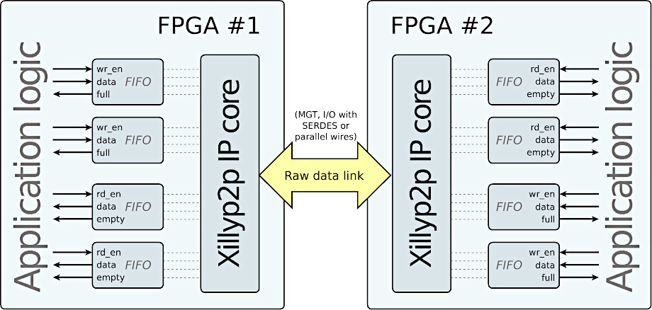
The diagram above shows how the IP cores on both FPGAs use the underlying physical connection in order to establish several independent data channels in both directions. This physical connection can be short (e.g. between two FPGAs on a PCB), but longer distances are also allowed (i.e. stretches that are typical to fiber optics). The Xillyp2p IP core divides the data bandwidth of the physical link fairly among the data channels in order to allow an efficient usage of this bandwidth.
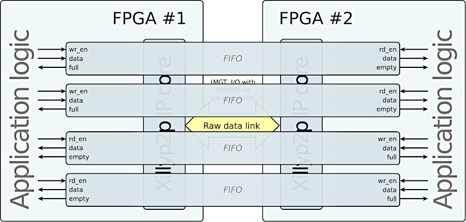
More interestingly, these IP cores also create an illusion of FIFOs that span across the two FPGAs, one such FIFO for each of these data channels. This illusion involves all aspects of a FIFO, including the reliability of the data exchange as well as the flow control signals ("full" and "empty").
Adding these imaginary FIFOs to the diagram from above:
These diagrams show a specific configuration with two data channels in each direction, however users will be able to generate custom Xillyp2p IP cores by virtue of the IP Core Factory. Just like Xillybus IP cores that are created in the IP Core Factory, custom Xillyp2p IP cores will be tailored regarding their interface with the physical connection, as well as the number of channels and their directions, their word width, and several other parameters that are related to each channel.
The physical communication channel
It is the responsibility of the user of the IP core to set up the raw link of data. Inside the FPGA, the Xillyp2p IP core interfaces with the raw link through a vector of parallel wires that represent the deserialized data on the raw data link. This is the common interface of MGT and other SERDES blocks, as facilitated by FPGA vendors.
The width of this vector is configured when the IP core is set up in the IP Core Factory, as any integer between 1 and 128 (inclusive).
The requirements from the physical channel between the two FPGAs are relatively easy: Any medium that transports data between the FPGAs at a constant rate and with a reasonable bit error rate (10-6 and below) can be used. The physical channel is fed with a data stream that is DC-balanced and randomized.
Examples of possible physical channels:
- A Multi-Gigabit Transceiver (MGT, sometimes referred to as a GTX), without 8b/10b or other similar encoding. None of the MGT's word alignment capabilities are required, nor any other advanced feature. The MGT may employ an equalizer that requires a scrambled data stream.
- A (preferably bidirectional) serial data link. In each direction, this link consists of a single wire or differential wire pair (e.g. LVDS) between the FPGAs. The FPGA's own SERDES blocks may be used to allow for higher data rates.
- A group of parallel wires that connect between the FPGAs. This allows utilizing several wires that are less capable for high data rates.
Hotplugging is allowed on the physical channel.
The Xillyp2p IP core implements several functions to ensure reliable data transmission, including a scrambler to randomize the data on the physical channel, alignment mechanisms, and a packet protocol that supports error detection and retransmission. In addition, it multiplexes the data from the various channels in order to imitate the behavior of a standard FIFO that appears to be split between the two FPGAs (as shown in the second diagram above).
A unidirectional version of Xillyp2p will also be available. Obviously, this version won't support retransmission, as there is no way for the transmitting side to know if the data has arrived correctly. However, all data that will arrive at the other side will be guaranteed to be correct: An error on the link will cause a halt of the data transport before the affected segment of data. The resumption of the data flow will require the intervention of the application logic.
Applications
- Connection between several FPGAs on the same board (using MGTs in particular).
- Connection between FPGAs through a backplane.
- Data acquisition, using an FPGA that is remotely located and connected by virtue of a fiber optic cable. For example, a remotely located video camera or radio signal (RF) receiver.
- Data output to a remote facility, by virtue of a fiber optic cable. For example, video output to displays that are far away from the image source, remotely located antenna for radio transmission, etc.
- Electrical isolation (for safety of medical equipment) by communicating with a front-end FPGA through a fiber optic cable.
- Data link with peripheral equipment through a cable (cameras, displays, sensors, radio transceivers etc.).
- Interfacing boards from different FPGA vendors by virtue of MGT or other physical connections that are present on both boards.
- Cost reduction of I/O-intensive applications by using several FPGAs with a moderate number of pins, rather than one FPGA with a high pin count.